Product documentation If you ordered accessories for your RFID reader, verify that they are also included with the order. Be sure to keep the original packaging in case you need to return the reader for service.
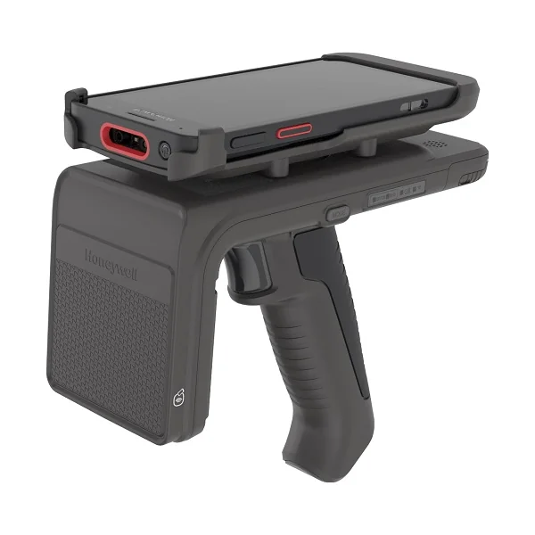
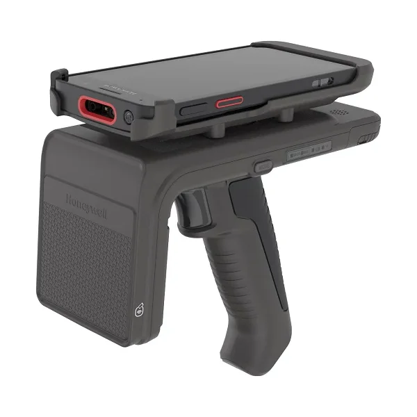
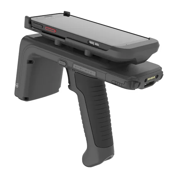
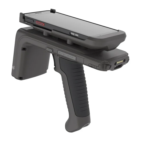
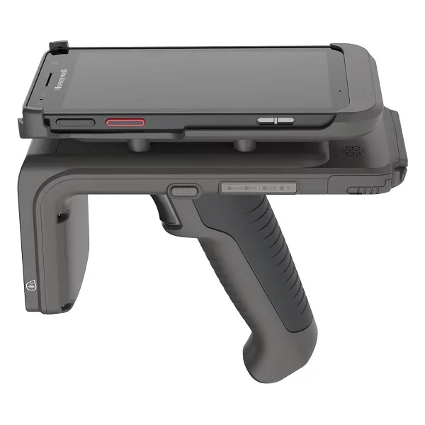
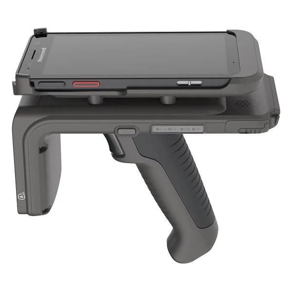
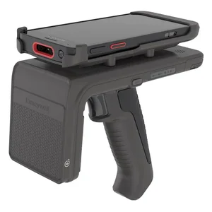
Reader provides Ultra High Frequency (UHF) Radio Frequency Identification (RFID) connected to a mobile terminal through USB and Bluetooth. The unit can read and write to UHF RFID tags. Note: RFID reader may differ slightly from illustrations depending on the model. 2 Bracket socket Power button Trigger UHF antenna Inserts for Bracket Attachment Screws Mode button Status indicators Charging contacts Battery release latches NFC Antenna Location 3 Battery Installation and Removal The RFID reader ships with a Li-ion battery manufactured for Honeywell International Inc. When installing or removing the battery, hold the unit upside down in the palm of your hand.
To access the battery compartment, squeeze the battery cover latches and slide the door out.
Squeeze the battery cover latches then slide the battery cover out.
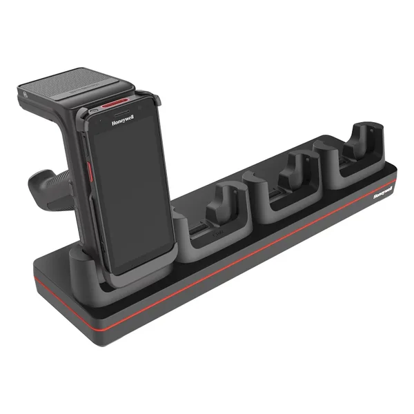
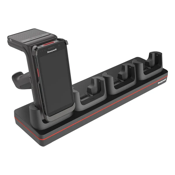
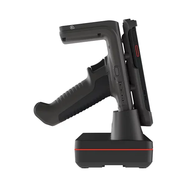
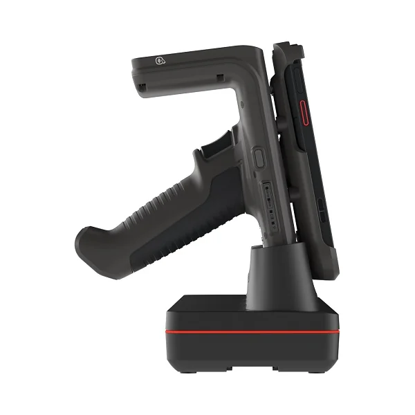
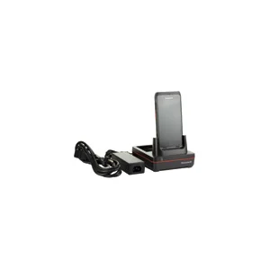
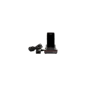
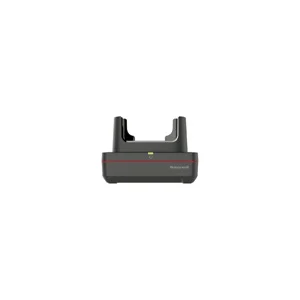
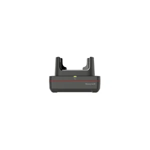
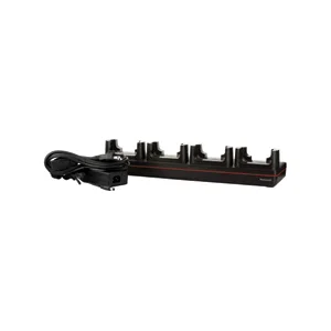
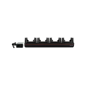
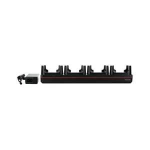
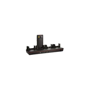
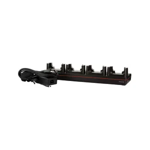
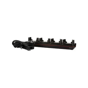
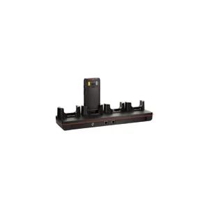
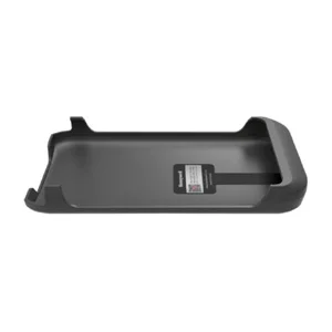
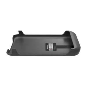
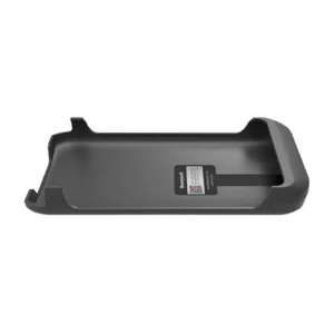
7 Charging Before using the reader for the first time, ensure the battery is fully charged. The IH45 RFID Reader is compatible with all existing CT40 charge bases and universal dock chargers. To charge the IH45 RFID Reader with a booted charge dock, place a non-booted device adapter sleeve into the charging cup. The RFID Reader can be charged alone or with a mobile device attached. If a mobile computer is attached to the IH45 when it is placed in the charger, both devices will charge simultaneously.
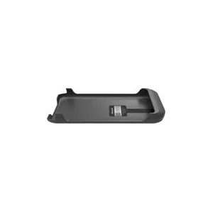
If the charge base has a booted cup, insert the device adapter sleeve into the charge dock.
9 Fitting/Unloading Bracket and Attaching Device Attach a mobile computer to the RFID Reader to connect in USB mode. To connect using Bluetooth, do not attach the mobile computer in a bracket. Before installing the device, ensure that the charge base plug and charge base socket on the reader are clean and free from dirt or debris.
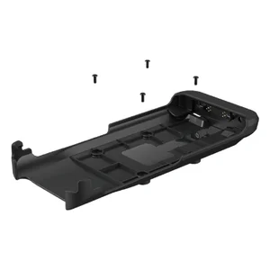
Align the bracket with the charge base socket and press the two parts together firmly until they click into place.
Insert the four screws provided with the bracket and tighten. Note: The attachment screws ship with the bracket for the mobile computer.
Using a different size screw than those provided with the bracket may damage the RFID reader.
Insert the mobile computer into the bracket and press it down. 11 Note: When installing the bracket, pay attention to the angle and pressure to avoid damaging the product.
Pull the mobile computer upwards out of the bracket.
To remove the bracket, hold the handle with one hand and lift the bracket up from the RFID Reader with the other hand. 13 Reading RFID Tags You can use the HonRFID application to demonstrate IH45 functions and tag operation.
Power on the mobile terminal and launch the HonRFID app.
Touch the Connect icon on the home screen to go to the Connect screen. Note: If the mobile computer is attached in a bracket that supports a USB connection, the unit will automatically connect by USB.
Use one of these methods to connect by Bluetooth: a. To connect manually, tap Search and wait until the available Bluetooth devices are displayed in the list then select IH45 to connect. b. To use Auto Connect, switch this function on then tap the Search button. The mobile device will search for the available Bluetooth device and connect to it automatically. c. To connect by QR code, tap the icon and select Barcode Way then scan the QR code on the RFID Reader. d. To connect by NFC code, tap the icon and select NFC Way then bring the NFC antenna on the mobile computer near the NFC antenna location on the RFID Reader. e. The unit beeps one time when successfully connected.
Tap CREATE READER at the bottom of the screen to pair with the IH45 and go to the Scan screen.
Press the MODE button and release within 3 seconds to check IH45’s operation mode.
If the RFID LED lights up, the IH45 is in RFID mode. If the 1D/2D LED lights up, the IH45 is in Barcode mode.
Note: The barcode reading option is only supported by Honeywell mobile devices. Switch on the Bluetooth function and Location (Settings > Security & location> Location) on the mobile device before connecting, or the connection will fail. The range (typically 0.2ft-20ft) at which a tag can be read depends on the tag type and size and the number of tags in the field. 15 MODE Button and Status Indicators Indicator Definition Press the MODE button to display the current mode indicator. Release the button within 3 seconds to turn the mode light off. Release the button: the current mode light is off. MODE MODE 16 Support Go to honeywell.com/PSStechnicalsupport to search our knowledge base for a solution or to log into the Technical Support portal. Documentation For the user guide and other documentation, go to sps.honeywell.com.