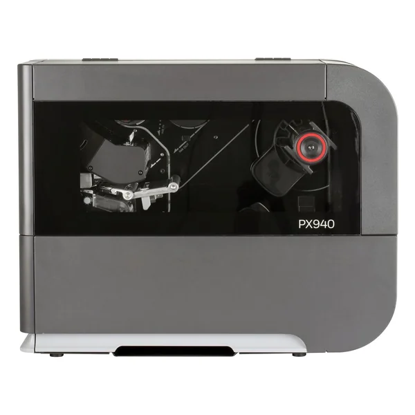
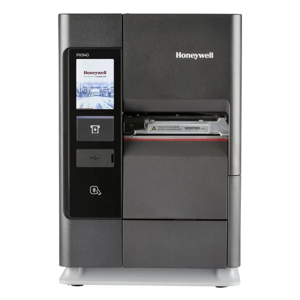
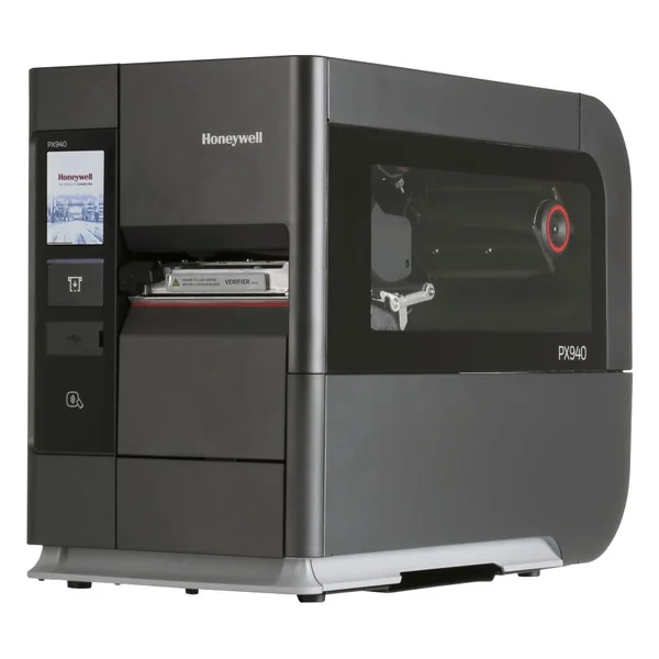
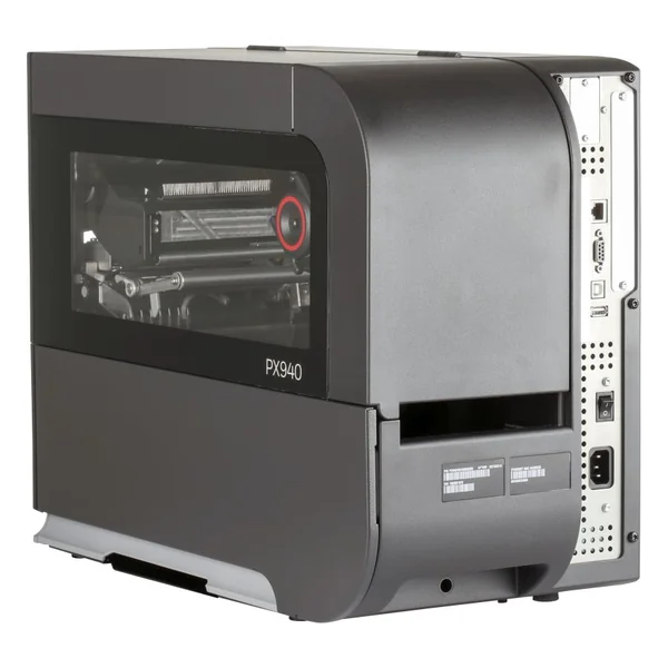
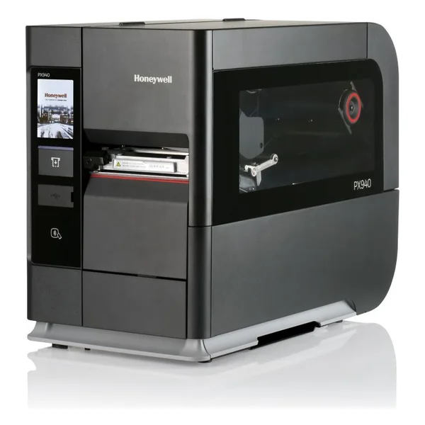
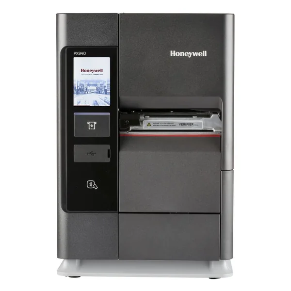
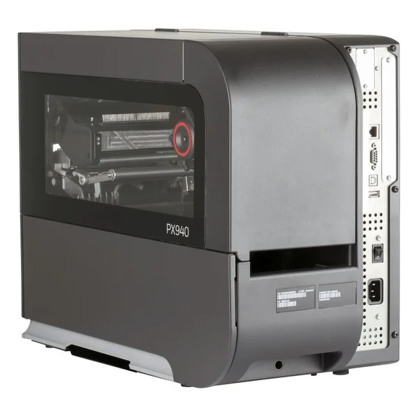
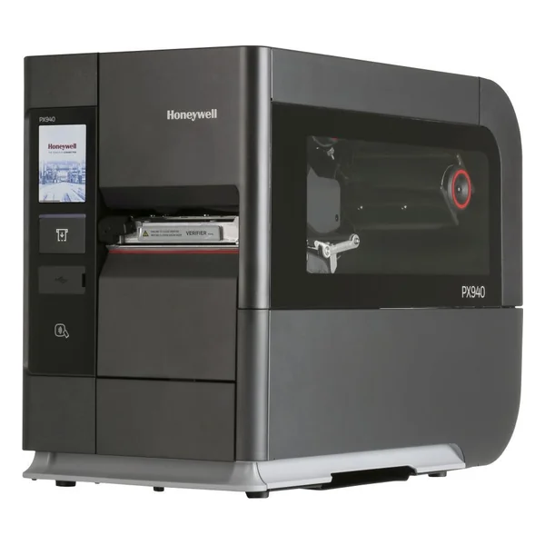
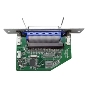
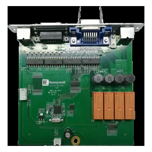
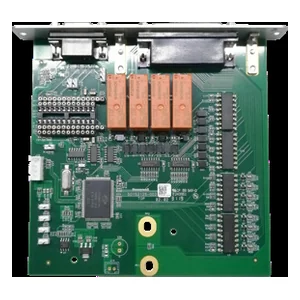
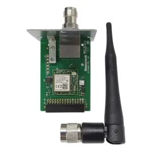
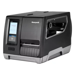
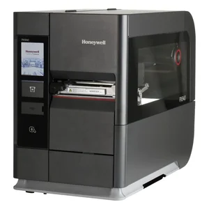
Applicator Interface Board For PX940 Installation Instructions 50158270-001 Rev B 03/20 PX940 Applicator Interface Installation Instructions 1 Introduction This guide describes the Applicator Interface kit for PX940 Industrial Series printers. Description The installation instructions describe how to physically install and configure the applicator board in the printer. Printer Firmware The printer must be fitted with Honeywell Fingerprint v8.60 (or later).
Two 4X8mm Torx screws The only tools required for installation are the #T10 and #T20 Torx screwdrivers. 2 PX940 Applicator Interface Installation Instructions Installing the Applicator Interface Board Follow the procedure to physically install Applicator Interface Board in the PX940 printer.
Turn off the printer and disconnect the power cord.
Use the T20 screwdriver to remove the two screws securing the electronics cover to the inside of the printer base.
Remove the two screws located on the outside of the electronics cover. Warning: The installation described in this section must only be performed by an authorized service technician. Honeywell assumes no responsibility for personal injury or damage to the equipment if the installation is performed by an unauthorized person. Follow ESD Procedures Caution: Follow standard ESD guidelines to avoid damaging the equipment.
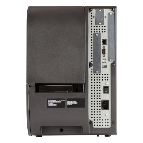
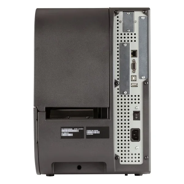
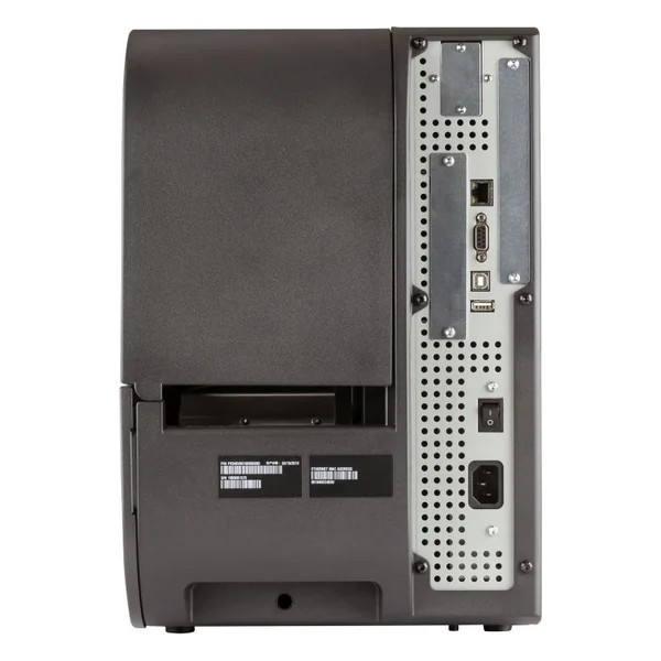
Remove the two screws on the back of the printer securing the cover plate and remove the cover plate.
Use the T10 screwdriver to remove the screw located on the top of the printer main board and replace with spacer screw.
Insert the Applicator Interface Board into the printer and secure the board assembly to the printer with two torx screws.
Secure the interface board assembly to the spacer screw with a Torx screw.
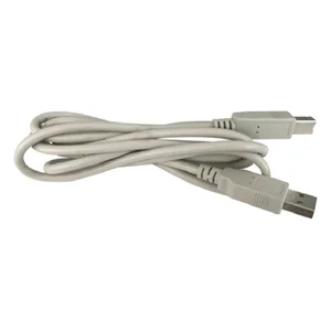
Insert the USB cable and power cable into the J37 and J33 connectors on the printer main board. Then insert the other ends into the J1 and J2 connectors on the Applicator Interface Board.
Put the electronics cover back on and secure it with the 4 screws. PX940 Applicator Interface Installation Instructions 5 Interfacing This option board contains 4 connectors for a Z-Style Port, a S-Style Port, an External Power Port, and an External Error Port. Z-Style Port Z-Style Port Pinouts Port Description Z-Style A D-Sub 15Pin receptacle connector.
Pin Signal Type Description 1 Signal groud Ground configurable for internal or external source 2 +5VDC Power Voltage supply for external sensors.
prints one and only one label whenever this pin is pulled to ground. Signal must be de-asserted and reasserted to print another label. Printing starts on HIGH to LOW transition if format is ready. De-assert this signal to HIGH to inhibit printing.
prints labels continuously when this pin is pulled to ground.
If a label is printing when de-asserted, printing stops after the label is complete. Assert LOW to start printing if format is ready. De-assert HIGH when current label has finished printing. Remains de-asserted while waiting for the next label to be ready to print. 4 Feed Input Assert LOW to feed label stock.
5 Pause Input Assert LOW for 200ms and then de-assert HIGH to toggle between pause and un-pause states. 6 Reprint Input Enables Reprint mode via software. When this mode in enabled, assert LOW to reprint last label. This input is ignored when reprint mode is disabled.
9 Ribbon/ Media low Output Goes LOW when the ribbon/media roll diameter drops below a predefined level, otherwise Goes HIGH.
Verifier failure action prompt 11 End print Output Drives an applicator or other external device requiring synchronization with the print cycle.
Mode 1: Asserted LOW only when media is moving, otherwise de-asserted HIGH. Mode 2: Asserted HIGH only when media is moving, otherwise de-asserted LOW. Mode3 (Default): Asserted LOW for 20ms when label has finished printing and positioned.
Mode 4: Asserted HIGH for 20 ms when label has finished printing and positioned.
12 Media out Output Goes LOW when the printer is out of media. 13 Ribbon out Output Goes LOW when the printer is out of ribbon. 14 Data ready Output Goes LOW when ready to print. De-asserted HIGH when printing stops after the current label. 15 Verification failed Output Goes LOW when the printer encounters Verification failed error.
Pin Signal Type Description 8 PX940 Applicator Interface Installation Instructions S-Style Port S-Style Port Pinouts Pin Signal Type Description 1 Media out Output Goes LOW when the printer is out of media. 2 Signal ground Ground Configurable for internal or external source. 3 Ribbon out Output Goes LOW when the printer is out of ribbon.
prints one and only one label whenever this pin is pulled to ground. Signal must be de-asserted and re-asserted to print another label. Printing starts on HIGH to LOW transition if format is ready. De-assert this signal to HIGH to inhibit printing.
prints labels continuously when this pin is pulled to ground.
If a label is printing when de-asserted, printing stops after that label is complete. Assert LOW to start printing if format is ready. De-asserted HIGH when current label has finished printing. Remains de-asserted while waiting for next label to be ready to print. 6 End print Output Drives an applicator or other external device requiring synchronization with the print cycle.
Type 1 (Default): Asserted LOW for 20ms when label has finished printing and positioned.
Type 2: Asserted HIGH for 20ms when label has finished printing and positioned.